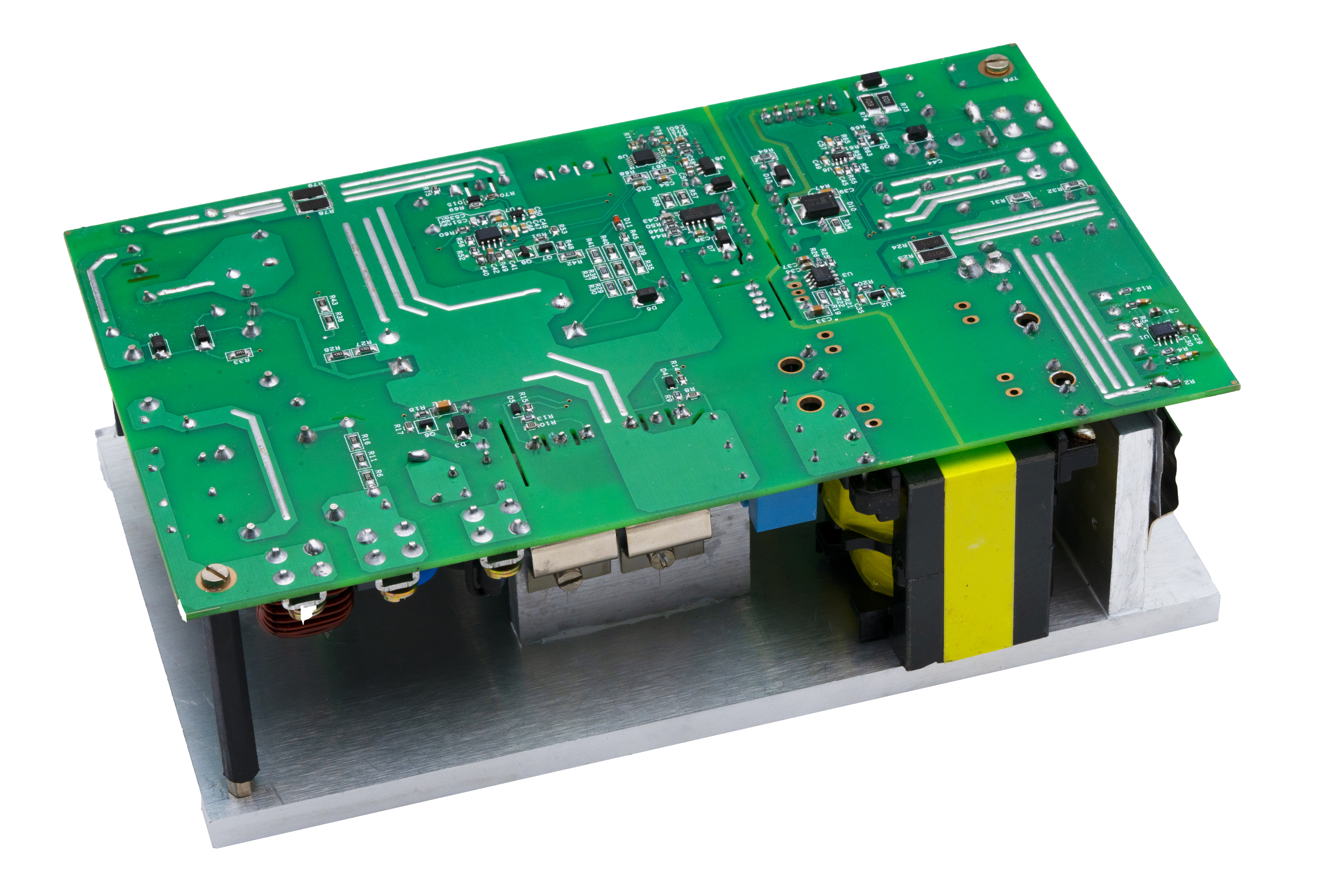
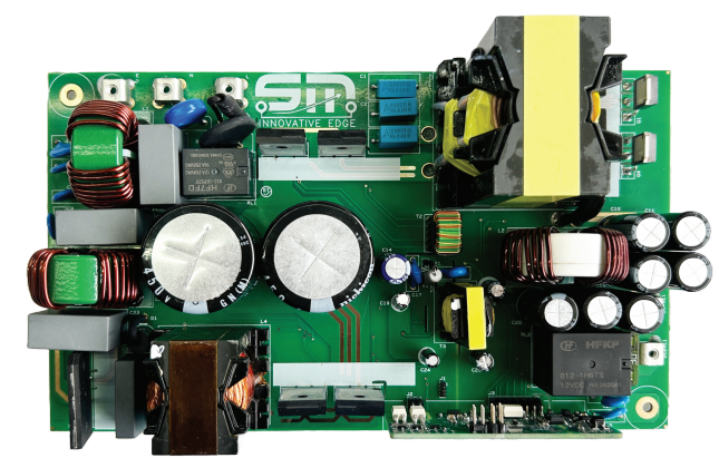
EV CHARGER - 2.2KW
Description
The off-board EV Charger with analogue boost PFC and digital half bridge LLC topology uses mathematical modelling to achieve high energy density, increasing safety, reducing weight, and improving efficiency, with precise control over output power.
It supports different battery types, and charging methods include pre-charge, CC, CV, CP, floating/trickle, and power exchange on CAN command.
Features
- Whenever REESS is connected for charging soft-start function is activated
- Charge voltage and current Cut-off to prevent the REESS from being overcharged
- Deep discharge condition of REESS is detected by pre-charge function
- Protects against input supply variation 120V ~ 280V with output de-rating feature
- On-board/portable charger have CAN, UART to communicate with BMS
- Over temp protection and added de-rating to prevent over heating
- Output short circuit and reverse protection
- Additional GPIO’s to interface LED or display
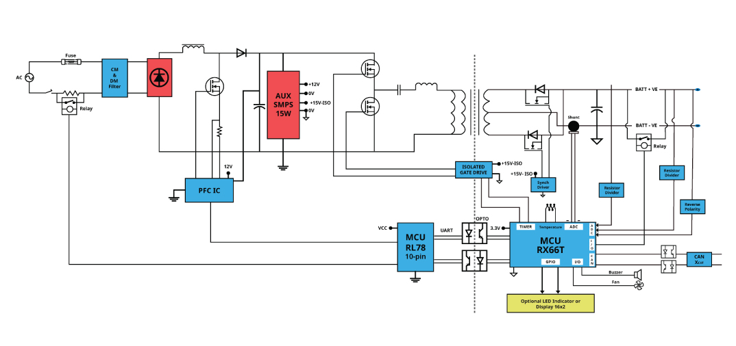
Block Diagram
Electrical Characteristics
| SPECIFICATIONS | VALUE |
|---|---|
| Max. Output Power | 2200W |
| Rated Power | 2200W |
| Nominal Input Voltage Range | 230VAC |
| Operating Range | 120V-280VAC |
| Input Current To The Charger | <18A |
| Input Frequency | 45 - 65Hz |
| Output Voltage Range | 35 - 60VDC |
| Rated Output DC Current | 35A |
| Max Output Current (33-60V I/P, Continuous) | 4A ~ 35A |
| Minimum Current Output | 4A @ Pre charge |
| Nominal Default Voltage | 60VDC |
| Voltage Tolerance | ±0.1VDC |
| Current Tolerance | ±0.5A |
| Efficiency @ >30% load | >=94% |
| iTHD | <5% |
| Power Factor | >=0.9 |
| No Load / Standby Power Consumption | <1.5W |
| Ramp Up/Down Time for 1V change | <100ms |
| Cold Start Time | <3s |
Safety
| PROTECTION | |
|---|---|
| Under Voltage & Overvoltage Without Jitter | Over Current & Short Circuit Protection |
| Surge Protection Type 3 Inbuilt TVS 6kV B72220S0301K101 | O/P Reverse Polarity Protection |
| O/P Overvoltage Protection: Cut off after 59 ± 1 V | Automatically Shut Down After Full Charge |
| Charger Thermal Shutdown: Calibrate based on Housing | Residual Current Protection through RCD: Optional in Adaptor Mounting |
| GALVANIC ISOLATION | ||
|---|---|---|
| INPUT-OUTPUT 2500 VAC, 50 Hz, 1 min, <10 mA | INPUT – Heatsink 1500 VAC, 50 Hz, 1 min, <10 mA | OUTPUT – Heatsink 500 VDC, 50 M ohm (min) |
Communication Features
| Communication Interface | CAN2.0B 500Kbps / Isolated CAN UART | Automatic Shutdown | Yes |
| Standby Power Of | Yes |
Display
| LED’s | Status Indications - Battery Status - Error and Fault Indication - SOC Indication in terms of % - 25%,50%,75% & 100% | REMARK |
| Can be customized as per the customer spec |
| Faults and Alerts | Alarms over CAN Bus. LED Indications Warning and Fault Handling Logic Can Be Implemented | REMARK |
| Can be customized as per the customer spec |
Test Procedure
| PROCEDURE | REMARKS |
|---|---|
| LPS | Tested |
| Power Factor Of PFC at Universal Operating Range | 120-280 |
| Constant Voltage Minimum And Maximum Range | 35-60 |
| Constant Current Minimum And Maximum Range | 4 to 35 |
| Soft Start Time | 1 Sec |
| Current and Voltage Protection | Tested |
| CAN Communication | Tested |
| Overall Efficiency | 95% |